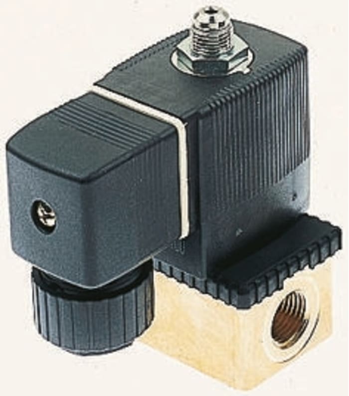
Electrovanne Burkert 6012, 24 V c.c., 3 ports , NF

Documents techniques
Spécifications
Brand
BurkertAlimentation
24 V dc
Nombre de ports
3
Taille de connexion
1/8in
Raccord
G 1/8" femelle
Commande
Direct
Position normale
NF
Type d'application
Gas, Liquid
Type d'application
3/2
Diamètre d'orifice
1.2mm
Matériau du corps
Brass
Série
6012
Pression de service maximale
10 bars
Gamme de température de fonctionnement
Maximum +55 °C
Filetage ou type de raccord
G
Température d'utilisation maximum
+55°C
Genre du raccord
Female
Temps de fermeture maximum
9ms
Facteur de débit Kv
0.045m³/h
Temps d'ouverture maximum
7ms
Pays d'origine
Germany
Détails du produit
Electrovannes miniatures NF 3 // 2 à commande directe, série 6012
Gamme d'électrovannes miniatures, modulaires, avec commande directe pour liquides neutres jusqu'à +100 °C.
Fonction NF 3 // 2, sortie DL, avec sortie d'échappement lorsqu'elles sont hors tension.
Possibilité de changer le solénoïde sans enlever la vanne.
Le solénoïde peut être positionné librement ou verrouillé dans 4 positions à intervalles de 90°.
Matériau d'étanchéité FPM (Viton) haute qualité en série.
Connecteur DIN 43650C.
Corps en laiton.
3 Way Inert Gases and Fluid Valves
Compact solenoid valves suitable for most gas and fluid handling applications. Where practical, valves are shown with a schematic diagram showing the (circuit) function. The diagram is laid out so that the left hand side of the diagram describes the valves operation when the coil is energised. When the coil is de-energised, the spring (or servo-assist) return controls the valve and this is described on the right hand side of the diagram, see the typical schematic diagram below.,The 3//2-way designation indicates a valve with three ports and two modes of operation. It is normal practice to refer to 2//2-way valves as two-way.,The port designations A, B, P, P1, P2 and R are used on the schematic diagrams and are marked on the valve bodies. Valve bodies are marked for a specific circuit function but can often be used for other functions. Reference to the schematic diagrams and technical specifications will indicate the appropriate connections and pressure capabilities should an alternative circuit function be required.
Prix sur demande
1
Prix sur demande
Les informations sur le stock sont temporairement indisponibles.
1
Les informations sur le stock sont temporairement indisponibles.
Documents techniques
Spécifications
Brand
BurkertAlimentation
24 V dc
Nombre de ports
3
Taille de connexion
1/8in
Raccord
G 1/8" femelle
Commande
Direct
Position normale
NF
Type d'application
Gas, Liquid
Type d'application
3/2
Diamètre d'orifice
1.2mm
Matériau du corps
Brass
Série
6012
Pression de service maximale
10 bars
Gamme de température de fonctionnement
Maximum +55 °C
Filetage ou type de raccord
G
Température d'utilisation maximum
+55°C
Genre du raccord
Female
Temps de fermeture maximum
9ms
Facteur de débit Kv
0.045m³/h
Temps d'ouverture maximum
7ms
Pays d'origine
Germany
Détails du produit
Electrovannes miniatures NF 3 // 2 à commande directe, série 6012
Gamme d'électrovannes miniatures, modulaires, avec commande directe pour liquides neutres jusqu'à +100 °C.
Fonction NF 3 // 2, sortie DL, avec sortie d'échappement lorsqu'elles sont hors tension.
Possibilité de changer le solénoïde sans enlever la vanne.
Le solénoïde peut être positionné librement ou verrouillé dans 4 positions à intervalles de 90°.
Matériau d'étanchéité FPM (Viton) haute qualité en série.
Connecteur DIN 43650C.
Corps en laiton.
3 Way Inert Gases and Fluid Valves
Compact solenoid valves suitable for most gas and fluid handling applications. Where practical, valves are shown with a schematic diagram showing the (circuit) function. The diagram is laid out so that the left hand side of the diagram describes the valves operation when the coil is energised. When the coil is de-energised, the spring (or servo-assist) return controls the valve and this is described on the right hand side of the diagram, see the typical schematic diagram below.,The 3//2-way designation indicates a valve with three ports and two modes of operation. It is normal practice to refer to 2//2-way valves as two-way.,The port designations A, B, P, P1, P2 and R are used on the schematic diagrams and are marked on the valve bodies. Valve bodies are marked for a specific circuit function but can often be used for other functions. Reference to the schematic diagrams and technical specifications will indicate the appropriate connections and pressure capabilities should an alternative circuit function be required.